T-Boner
May 26 2016
Here's T-Boner, my latest 12# combat bot designed for Dragon*Con Robot Battles. This will probably replace Omega Force. The competition has improved considerably since Omega Force was built 10 years ago so I really needed something new to keep up.
It uses brushless motors for driving both weapon and wheels and is powered by five Lithium Ion 18650 cells (LGDBHE4 18650) providing 18 volts and 2500 mAh. I used Afro 30 amp ESCs from Hobby King with Simon K firmware to control the motors.
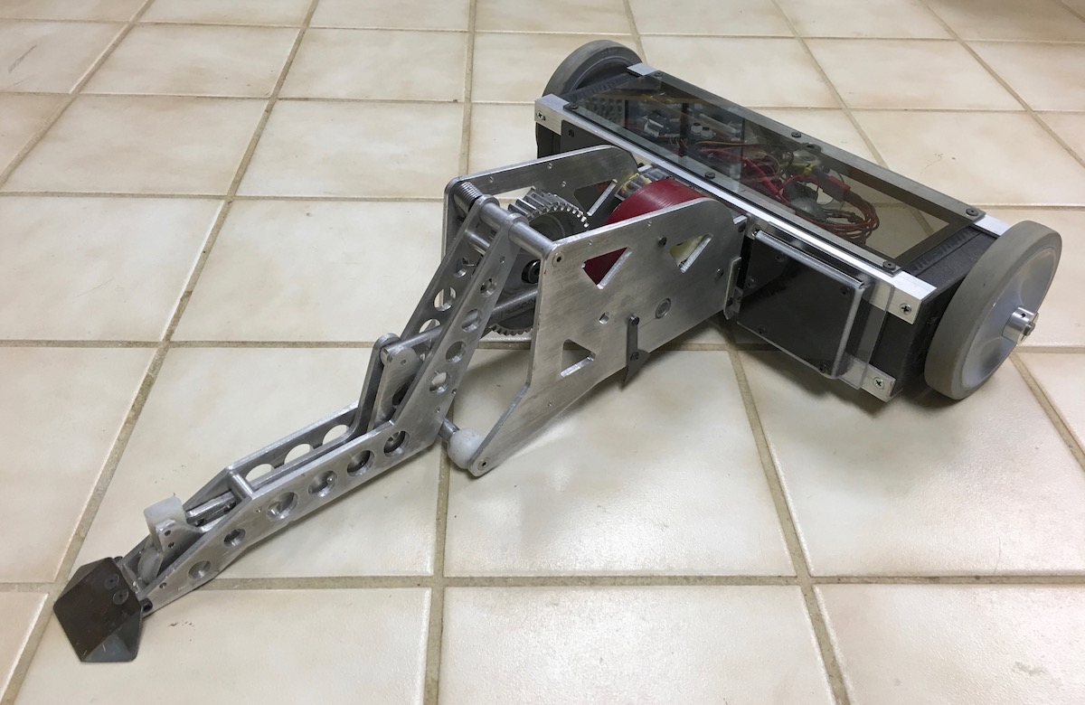
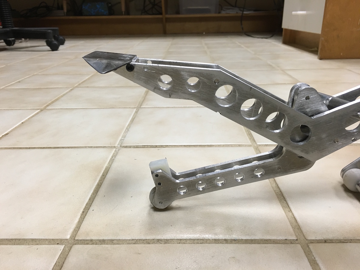
The weapon is a self activated scissor flipper powered by a 1.5 x .25 inch flywheel spinning at 35,000 rpm. It stores 70 Joules. The flipper is triggered when the opponent pushes the small peg sticking up just behind the steel wedge. If the bot gets flipped over the whole weapon module can self-right by rotating 180 degrees. I can also tilt it a few degrees left or right with the left joystick on the controller for navigating certain Robot Battles stage hazards.
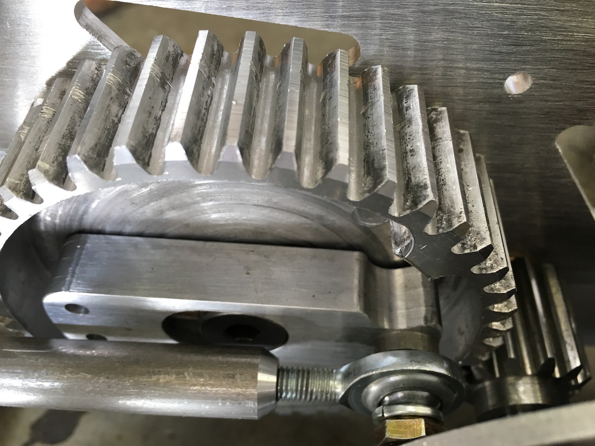
This is a closeup of the dog clutch assembly. The large gear continuously spins clockwise at 725 rpm. When the opponent pushes the trigger peg the spring loaded horizontal bar moves to the right and engages the inner tooth which pulls the bar and pushrod around about 120 degrees in 27 milliseconds before automatically disengaging.
Here's a wider angle view of the weapon.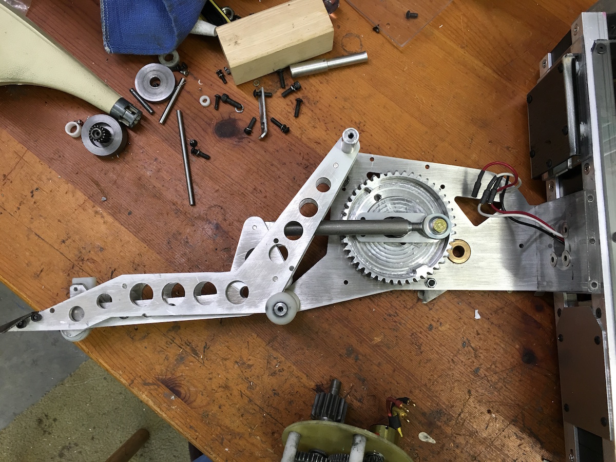
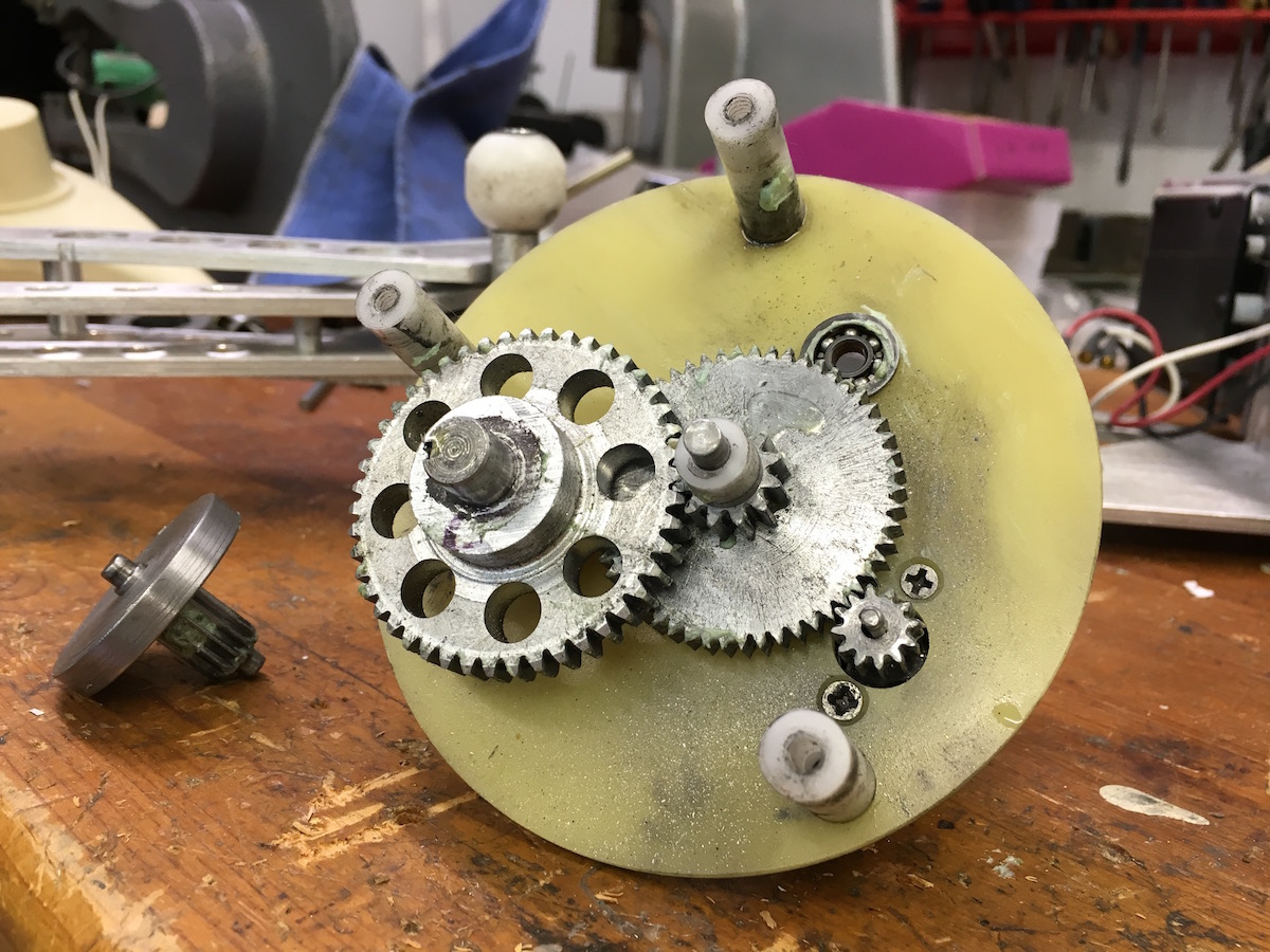
This is the weapon gearbox shown with the flywheel removed. (It's sitting on the bench to the left) Total reduction is 12.94 : 1 . This drives a 12 tooth gear that engages the large 45 tooth external weapon driver gear for an overall reduction of 48.5:1. The end plate material is garolite the spacers are Delrin. Electrical power is pretty low. After the flywheel gets up to speed the motor only pulls 2.6 amps at 18 volts.
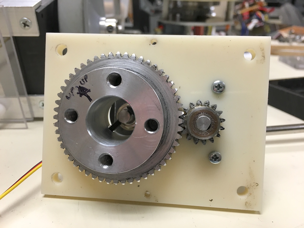
This is the inside of the gearbox that self-rights the weapon assembly. The weapon bolts the the four 1/4-20 holes and motor power wires are routed through the large center hole. There is a 10K precision servo pot shaft centered in the hole with a screw at a right angle engaging a slot. It's powered by a 70:1 gearmotor I got from Pololu, part #1105. The servo control is handled by the main processor, a Teensy 3.2 .
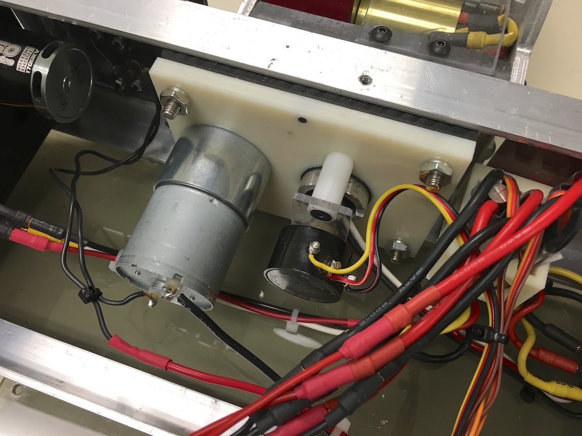
Here's the other side showing the motor and pot. To prevent hardware or software failures from causing continuous rotation I installed a couple of limit switches (not shown).
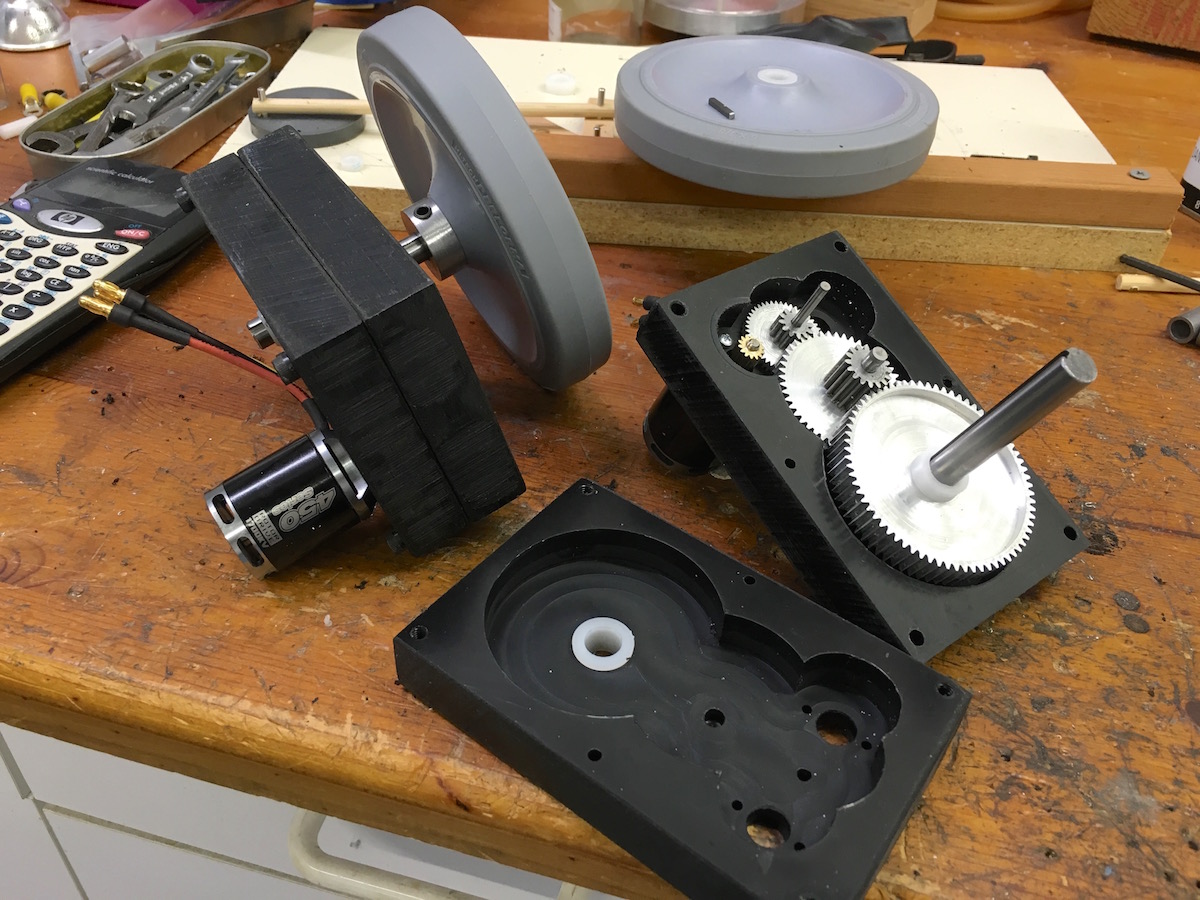
These are the drive units. Those are 5 inch Colson wheels on 3/8 inch shafts. Motors are 1700KV outrunner brushless geared down 62.5:1 . This gearing turned out to be a little to fast and I had to limit the speed in software to keep the bot controllable on the Dragon*Con stage. The cases are CNC machined ABS.
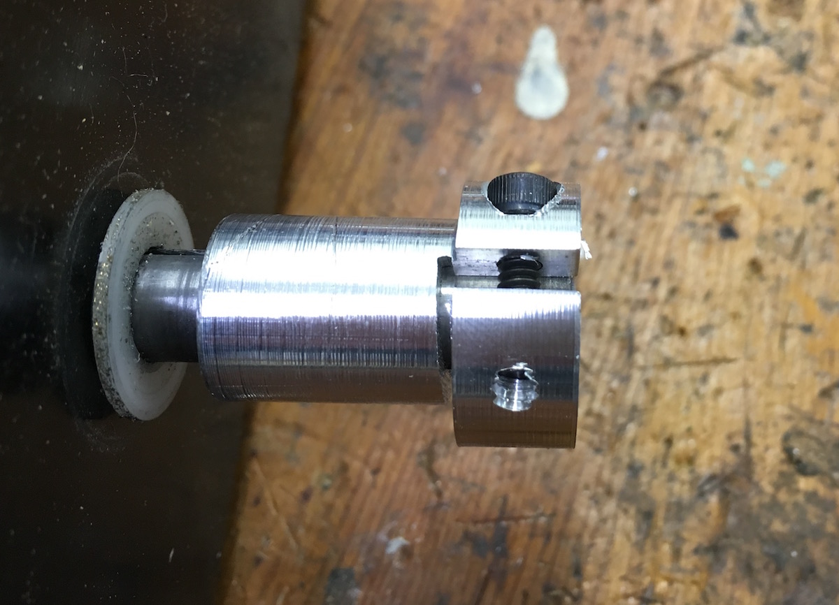
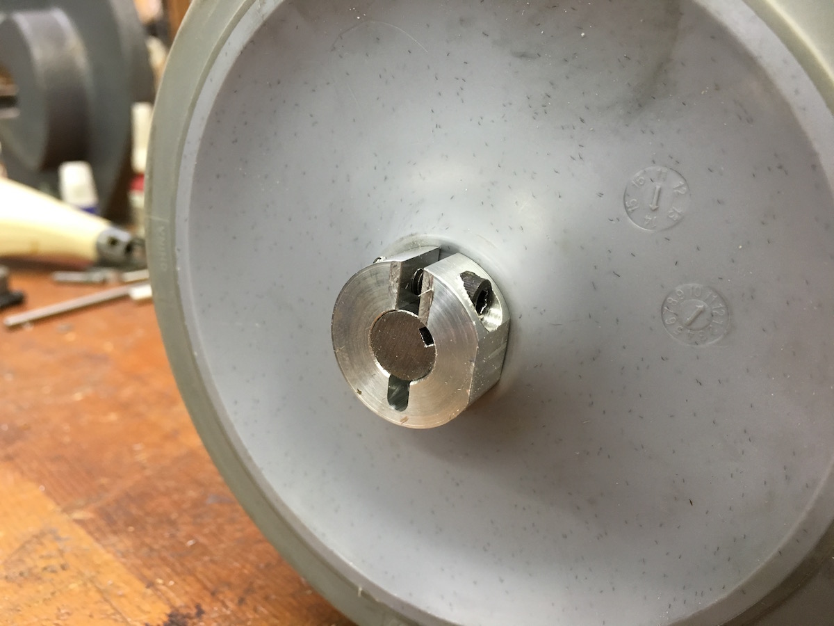
This is a homemade wheel hub and clamp for the Colsons. It was made with the lathe, mill and bandsaw. I first tired a set screw and square key stock but it kept coming loose. This works much better.
Here's a picture after it was press fitted into the wheel hole.
To help prevent unplanned stage dives I installed spur brakes on the weapon frame. They will dig into the stage carpet when the front end starts to drop.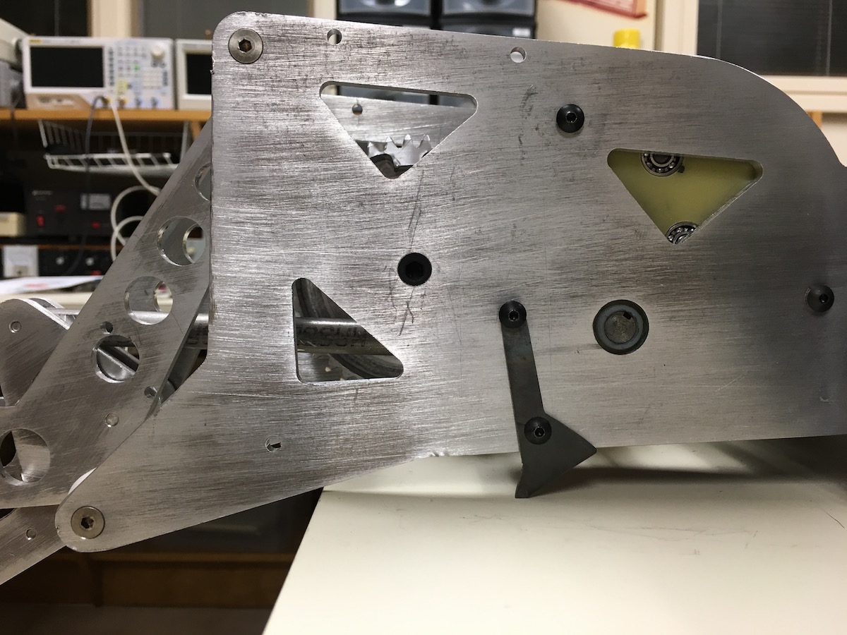
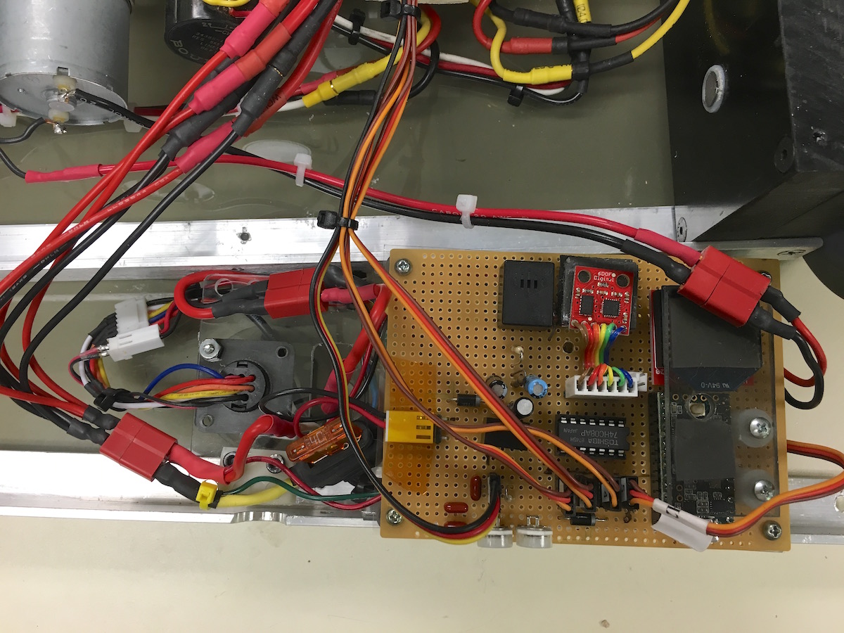
Shown below are the electronics. I use a Teensy 3.2 processor board to control everything. With 32 bits, 64K flash and 256K ram running at 96 mhz it's overkill for this application :) An Xbee radio receives commands from a modified game controller. The Xbee and Teensy are held in place under a piece of Lexan to keep them from falling out of the sockets. There is a small speaker that emits beeps to remind me to turn off the power so I don't kill the batteries.
Mounted on a shock mount is a module with an accelerometer and rate gyro. The accelerometer is used to determine when the bot is running inverted so it can reverse the controls and rotate the weapon 180 degrees. I use the rate gyro as negative feedback to the steering to greatly reduce sensitivity and make the bot easy to control.
A couple of trim-pots set the weapon speed and trim the weapon position so the wedge is flat on the ground. Not visible below the perfboard are the Sabertooth brushed motor controller for weapon self-righting and a small switching power supply to provide 12 volts to the self-righting stuff.
There's a 40 amp fuse to keep it from going up in flames if something shorts out.
Three Afro 30 amp brushless ESCs (not visible here) deal with running the motors. They have modified Simon K firmware.
I'm making a PC board to replace the perfboard.
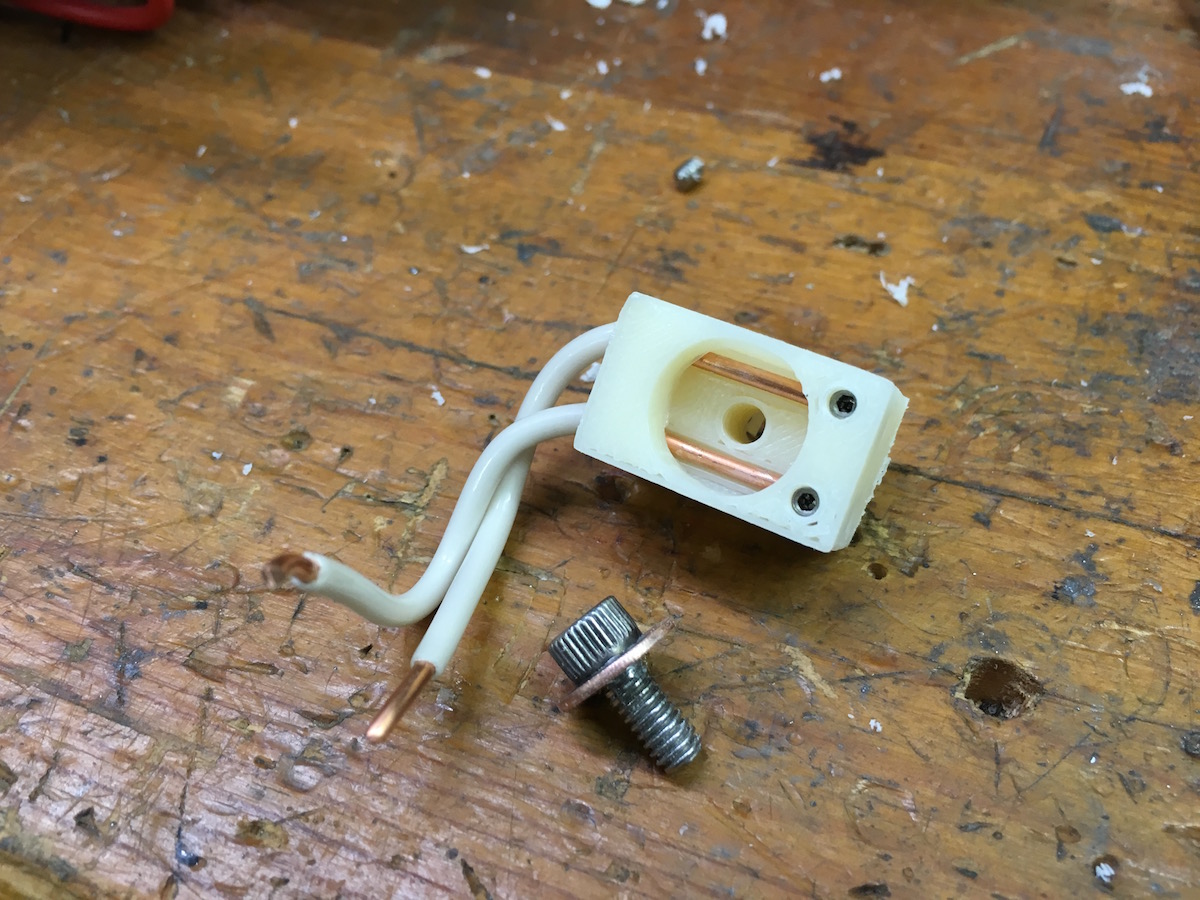
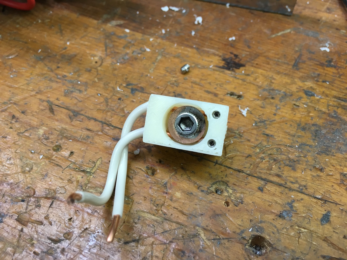
Because the four speed controllers all have large value capacitors across the power inputs the current surge at turn-on is insanely high. A couple of power switches I tried failed with welded contacts in short order. So, I used my 3D printer to make a power switch. That's a copper washer soldered to a screw. It's principle of operation should be obvious.
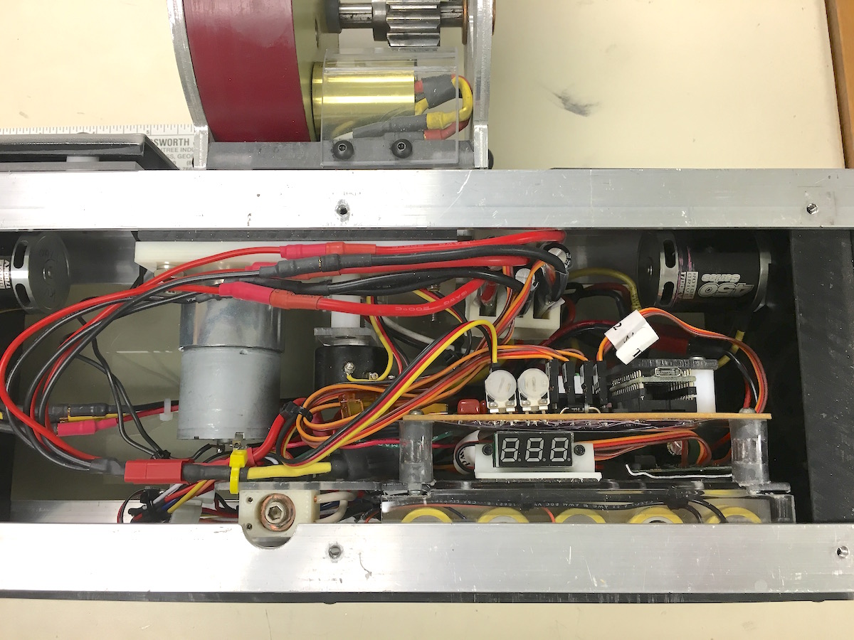
Everything assembled except the top cover. The 3 digit display is a voltmeter connected to the battery.
An early testing video
T-Boner did pretty well at Momocon taking 2nd place after being defeated by Tetanus Shot in the final. There are some electrical/software problems to be solved. The processor crashes frequently when the batteries are fully charged but rarely when partally depleated. It might be a ground loop or ground bounce, I don't know yet.
This bot has recently been improved! Click here to see version 2.0
All photos on this page were shot with an iPhone 6s.
Hit Counter = 12835
Previous page: T-Boner 2.0
Next page: Electric Whirligig
